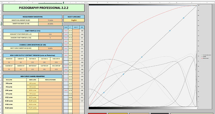
Hi, I’m using the Piezography DN pro system, pro ink, the new linearization tool, etc to print Pt/Pd. I’ve been working under the same conditions and iterating a curve. It keeps swinging wildly, I’ll limit, measure, make a new curve and all my whites are blown out, I’ll measure that one, make a new curve and it has swung in the other direction. I’ve started over multiple times with the same result. I’m wondering if my problem is that the white point my i1profiler is using is so far from the white of my Arches Platine. Should I be using the white point disk that comes with the i1Profiler or should I do the white point calibration on a uncoated part of my paper? Thanks!
You calibrate on the i1 profiler’s white plastic calibration disk.
A few workflow questions…
-
Can I assume that before you began linearizing that you have first established your correct standard exposure time or unprinted Pictorico Ultra Premium OHP film?
-
What is the name of the PiezoDN target that you are printing on film to contact print with?
-
What is the name of the starting Curve you are using to print that target?
-
From which application are you printing this target?
After these answers I may want to see your spreadsheets…
best,
Jon
Checking back in on you about this…
Hi Jon,
I’m sorry for the extremely delayed response, some life stuff got in the way, I appreciate your patience. Here are my answers to your questions in blue
You calibrate on the i1 profiler’s white plastic calibration disk. Great, that’s what I’ve been doing
A few workflow questions…
-
Can I assume that before you began linearizing that you have first established your correct standard exposure time or unprinted Pictorico Ultra Premium OHP film? Yes, and I’ve been using the same exposure time on the same unit.
-
What is the name of the PiezoDN target that you are printing on film to contact print with? I used the PiezoDN Limiter Target to begin with (printed with the Pro-PiezoDN-PtPd-DevOut) and followed the limiting instructions in the digital negative part of the PiezoDN manual.
-
What is the name of the starting Curve you are using to print that target? Pro-PiezoDN-PtPd-DevOut
-
From which application are you printing this target? I use Print-tool
I follow the manual as closely as I can, I use the pro ink set, I keep my chemistry the same, I print on Platine, and I use a i1Pro for all my measurements. I’m happy to send you whatever documentation would be helpful!
Thanks so much for your help,
-Lyra
You do not use a Limiter Target unless you are limiting the inks which you do not need to do with Pt/Pd.
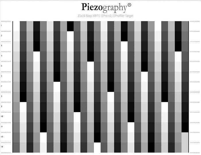
You should begin from scratch and use the target: Piezography-21x16step for the instrument you are using.
Begin by printing it with a fresh unadjusted copy of the Pro-PiezoDN-PtPd-DevOut curve.
Copy the data out of the Pro-PiezoDN-PtPd-DevOut curve and paste it into Starting Curve.
Measure it and put the CGATs data into Measurements.
Copy the New Curve and paste into a text editor and save as your 1st-New-Curve.quad or your name choice.
Use this new .quad to reprint the same target image.
After processing read the data.
Copy the data from 1st-New-Curve.quad and paste it into Starting Curve of PPETv2
Paste the newly measured CGATs data into Measurements.
It creates a New Curve - call it 2nd-New-Curve.quad or whatever.
Use this new curve to reprint the Piezography-21x16step to see if you are fully linear (this is called the validation).
After processing it measure it.
Copy the data from 2nd-New-Curve.quad and paste it into Starting Curve
Paste the new CGATs data into Measurements
If you are satisfied how linear you are your 2nd-New-Curve is your final.
If the results are a bit more linear for you then copy the New Curve data into a text editor and save as your Final Curve…
Hope this helps!
Jon
Wow, such a fast reply, thank you!
I used the limiter because my whites were totally blown out, when I printed the limiter the first square I could see was in the 230s (I’ve done the process before in another darkroom, did not use the limiter and had the same problem of the curves vacillating back and forth so thought I’d try limiting first). Any thoughts given that my first print with the straight curve is always on the blown out white side? By PPETv2 I assume you mean the Piezography Professional 2.2.2.xlsb? Except for not limiting, the rest of the process is what I’ve been doing and the curves just keep swinging from one side of linear to the other. In the last darkroom I used the 21 x 16, this time I’ve been using the 256 step tab to measure thinking it would be more accurate. Is there a downside to using the 256 vs the 21x16?
Thank you!
-Lyra
First the target - I assume you are hand coating and therefore you can not perfect the application of the sensitizer as would a calibrated machine roller coater. Therefore you measure multiuples of fewer patches at different locations on the sensitized media and have the software average them all together. It is rare that anyone can apply the exact same amount of sensitizer to every square cm of a media. Therefore the density varies and with a 256 patch there will me too many measurements that are inadequate due to hand coating variations (rod or brush).
Limiting is better suited to actually knowing too much ink jet is being applied to the film as per evidence the film can not absorb it.
Almost all PPET Pt/Pd calibrations start off with blown highlights… but I think that if you look very closely at measurements you would see there is some data there and it is not necessarily still paper white.
Gotcha, thank you! When you say you measure multiples of fewer patches, does the Piezography-21step-i1Pro.pwxf ask you to do that (ie have space for multiple measurements per square?) I don’t see a place in the pro 2.2.2 software where it would average them. (I’ve only used the Piezography-256step-i1Pro.pwxf)
No it does not. It is the 21x16 target that represents " multiples of fewer patches" and it happens automatically in the PPET. It is literally a 21 step target multiplied 16 times on the target.
Awesome. I’m using an i1Pro1 but in my Pieography images folder only has 21x16 step .tiff and .pwxf for i1Pro2 and i1Pro 3. Is there a version of both for the 1iPro1?
Thank you!
-Lyra
You could use the i1Pro 2 target for the i1 I believe the aperture is the same size as the 2.
Thank you, I’ll try it!
Hi Jon,
When I load the 21x16step-i1Pro2.pwxf file into i1Profiler it looks for a i1Pro 2 device (and I have i1Pro 1 not 2), so using the v2 for a v1 device won’t work. Is there a version for the i1Pro1 and if so will it work with the i1Pro2.tiff I printed?
Find the file on your computer: Piezography-21x16step-i1Pro2.pwxf and open it in a text editor like Sublime or BBEdit.
Search for the text MeasurementDevice=“iPro 2”
and change it to MeasurementDevice=“iPro 1”
if that does not work
change it to. MeasurementDevice=“iPro”
let me know if that is a quick fix
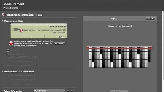
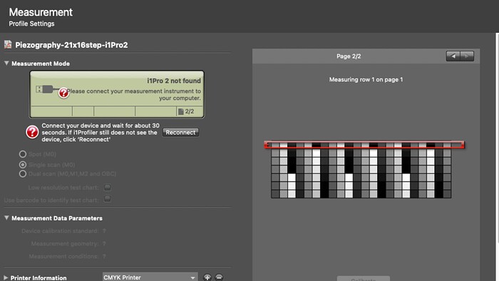
Hey Jon, that seems to have worked, thanks! However the measurement chart I see still doesn’t match the target I printed and I’m note sure how to measure in a way that fits the grid (the one I sent screenshots of).
Send me screenshot of Profiler.
Hi Jon, I replied via email but just checked here and my reply isn’t showing up. I’ll try to attach them here. Let me know if you have trouble opening them.
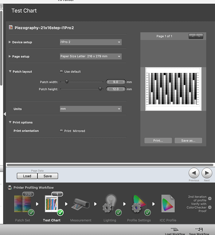
yours is a page setup issue. go backwards to “Test Chart” option and select letter sized. should fix that easy enough.
Thanks so much Jon, that worked (although for some reason I had to change the patch width to 7.3 to get it to match the layout of the print). I ended up with a ton of FALSEs in a way where if I fix them it dramatically changes the curve. Should I leave it as is?
Below is a screenshot of the FALSEs, and a side by side of the original curve and the new curve made without fixing any of the FALSEs.
Do not fix the false but use the new curve to print the target a second time and validate whether you are linear or need a second iteration (which is very normal). Your target was very light. Normally for Pt/Pd we do a third…
So when you print the second contact print with the new curve, process, dry and measure it…do not forget that Starting Curve will now be the new curve you printed the second contact print with. and so on - through the final… You are not using measurements each iteration on the original curve. ALWAYS “Starting Curve” is whatever curve you used to print the target.
