(Re-posted here from my original post on the QTR Yahoo Group as requested by Walker. I’ve also added a few minor clarifications.)
I’ve discovered what I think is a problem with QTR Calibration Mode that is exposed when using the 10-channel ink separation TIF file, and I’m wondering if anyone else has seen this or has an idea of what is happening.
I’m printing with Piezo Pro inks in my 7900 10-channel printer. The Green channel is mostly dead and that line is loaded with Piezoflush. All the other 9 channels have PiezoPro ink, and print perfectly.
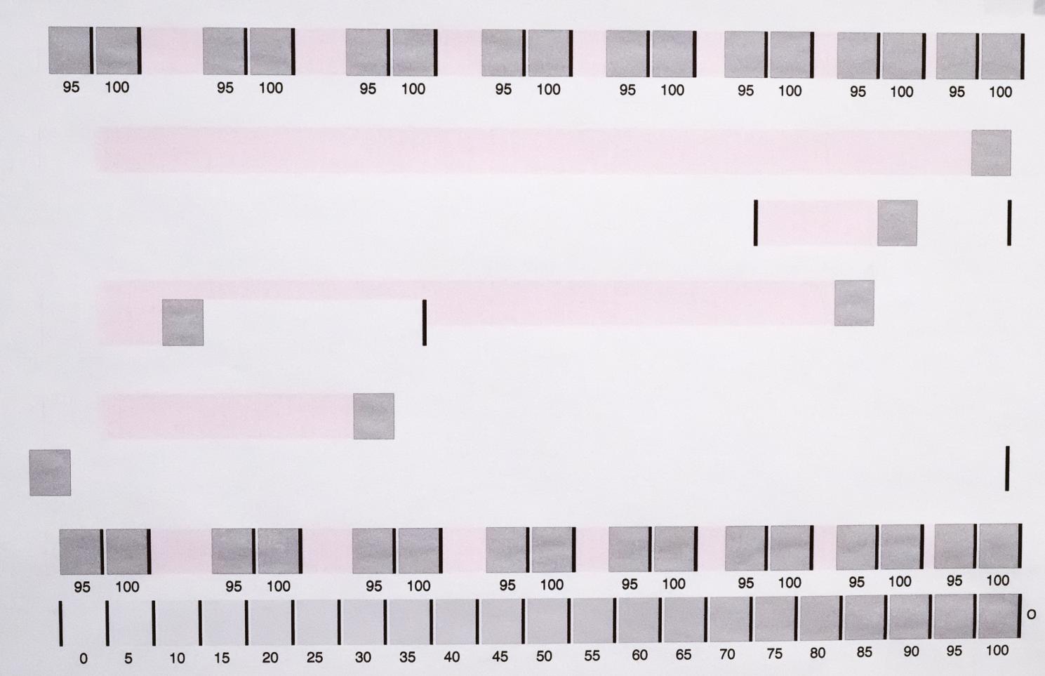
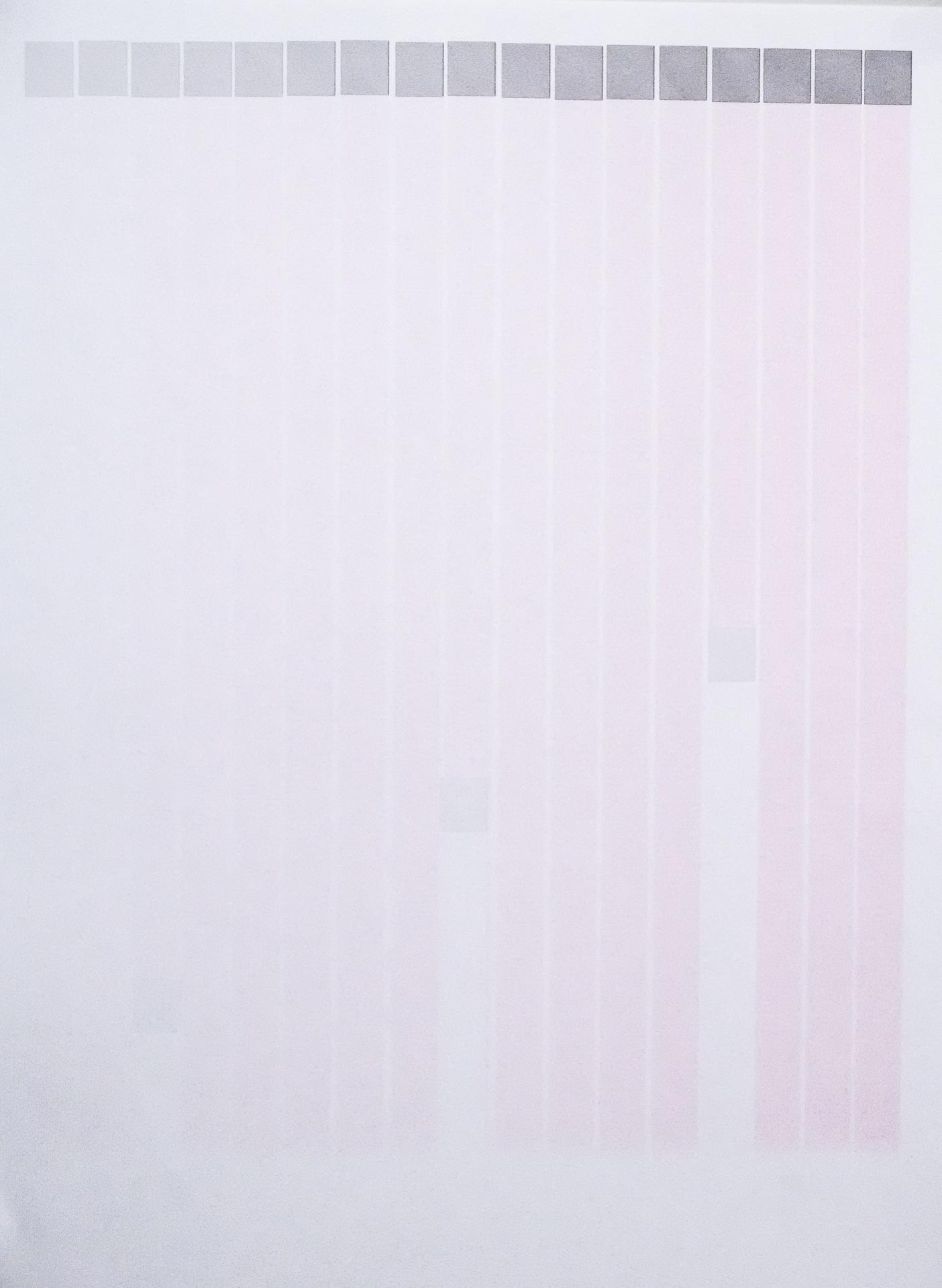
When I print a 10-ink separation image in Calibration Mode, everything looks as expected except in the Orange channel. In the Orange channel I have the PiezoPro Cool Very Light ink installed. The Cool Very Light patches are printing fine, but I’m seeing a really weird “overlay” of ink from the Green channel which prints very light pink in my case since the Green channel has Piezoflush installed. The pink is VERY light, but I think this is because I have only about 1/4 of the Green nozzles firing. I initially noticed the pink in the thin white spaces between each of the Orange channel patches, starting at about 55% and then up to the last 100% patch. The pink density is increasing in proportion to the density of the patches as you move towards the last 100% patch.
I did a lot of testing with various custom ink separation files to characterize the problem. To illustrate what is happening, I made up a special TIF file of the ink separation image containing only the Orange row of patches and then a number of single 100% Orange patches (without the dark black separator line) placed around the page. I printed this in Calibration mode, then made a quick photo of that which I’ve attached. Note, because of my bad photo, you probably won’t be able to see any pink in the thin white line between the patches, but it is there. The important thing is to note the pattern of where the pink overlay (Green channel) is happening and also NOT happening. (NOTE: This test image was printed on cheap copier paper so it’s not ideal, but at least you can see the pattern of what is happening.)
Be aware that the page is printed from right to left, i.e. the right edge is loaded pointing down in the printer. That’s important to know, because what I’m seeing is that immediately after a patch of the Orange channel ink is printed, the printer is laying down ink from the Green channel. This should NOT be happening. Furthermore, you can see where I placed a solid black line (which is from a different ink channel) the pink overlay (Green channel) stops. It’s as if the rasterized calibration image being sent to the printer is somehow including Green channel data AFTER any Orange channel patch up until a different object is encountered which uses a different channel. Very strange!
At first I thought there could be something going on with the printer head itself since the Green channel is already bad and the Orange and Green channels are co-located on the head and share the same cover in the capping station. But the unique pattern revealed in my tests tells me that the raster image being sent to the printer most likely includes the bad data. I think this is a software problem, not a hardware problem.
Has anyone else seen this kind of issue printing 10-ink separation images in Calibration mode? Not sure if it matters, but I’m running QTR on Windows 10 64-bit. Any ideas appreciated.
Dave

